

We have learned that unfortunately it is common to have different color output for the same device, even with the same specific model. But in practice, it is necessary to have all devices reproduce the same output. Being able to achieve consistent colors across different devices and media is a big challenge…
So, what can we achieve when implementing “color management”? In short, we can expect a similar appearance of an image across different devices and media; just like what is shown in Figure 1. All devices, including input devices, such as scanners and cameras, and output devices, such as monitors, projectors and printers, will all reproduce the same color appearance. In order to do so, it is necessary to understand the range of colors that a particular device or medium could reproduce. The range of colors is called “color gamut”.
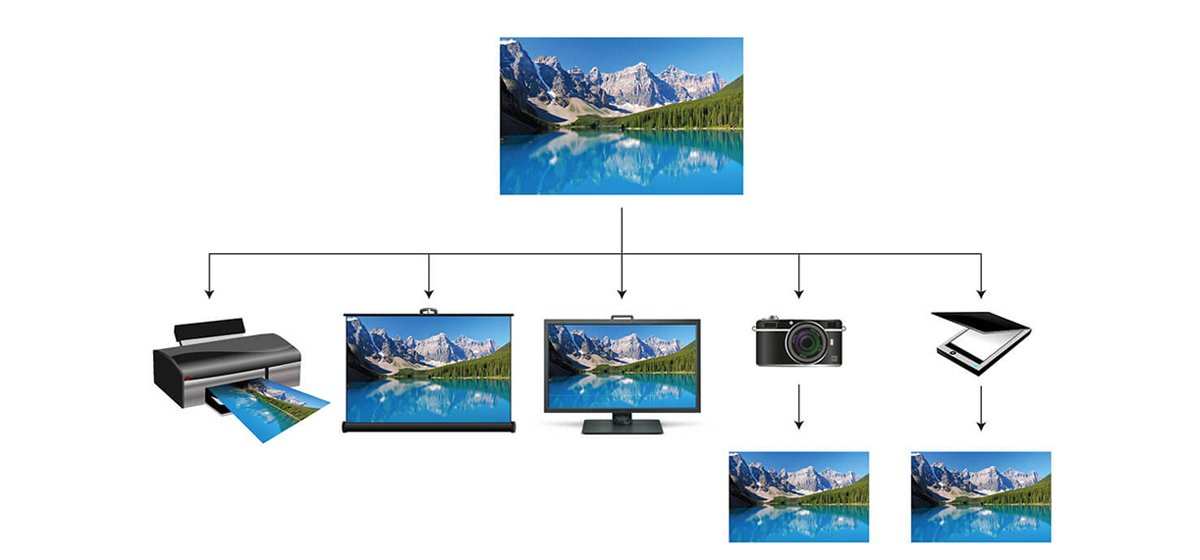
Figure 1: Same color appearance across different devices and media.
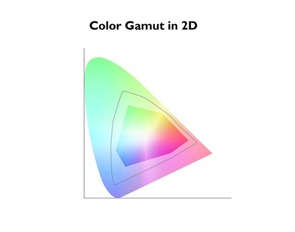
Figure 2-1: Color gamut in 2D.
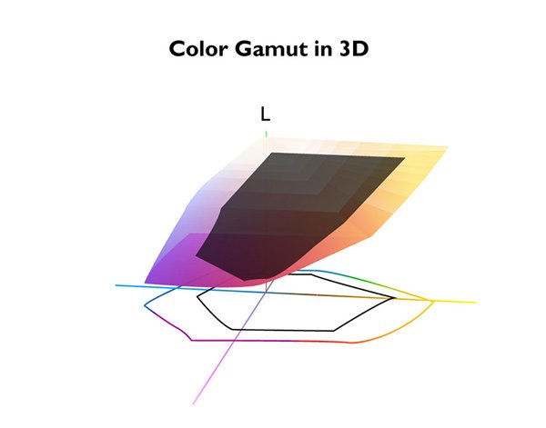
Figure 2-2: Color gamut in 3D.
Color gamut is usually described as a 2D diagram, shown in Figure 2(a). The horseshoe shape represents all the colors that humans can perceive, and the enclosed area inside the horseshoe shape represents all the colors that a device or medium can reproduce. But in fact, colors should be described in 3D since we need to use XYZ values to describe a particular color. The comprehensive color gamut should be drawn in 3D, like the one shown in Figure 2(b). However, due to the fact that drawing in 3D is not easy, even with the latest computer tools at our disposal, the 2D color gamut diagram is still widely used. The unfortunate result is that the lightness information of the color is missing in the 2D diagram. So, if there are two colors shown on the same location, it may not necessarily be the same color: it could be the same shade of color, but one may be lighter, and one may be darker.
For two devices to have the same color output, it is necessary to accurately map or transform the two color gamut types. Failure to do so, can result in the situation illustrated in Figure 3, which is a very commonly seen scenario of unmanaged colors. There are many algorithms out there to map or transform color gamut types, but we are not going to discuss these in depth here. What we will discuss is the concept of color management and its general workflow. More importantly, what tool can help us manage colors.
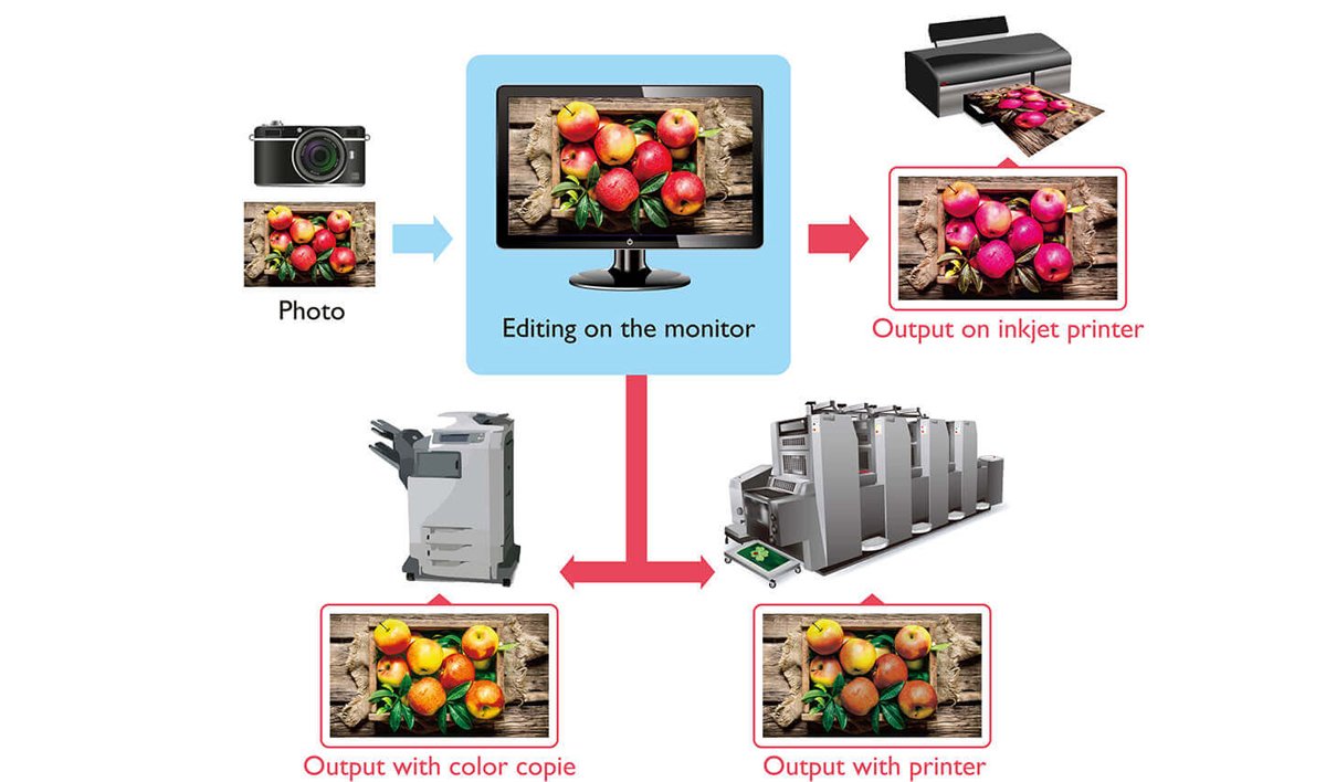
Figure 3: Example of unmanaged colors.
When transforming or mapping two color gamut types (or devices), it is simple; just setup one transformation between the two devices, and we are done. But what happens when there are more than two devices? We could still setup separate transformations between each pair of devices, but this will result in a very messy web of transformations; like the one shown in Figure 4. In order to reduce this complexity, it is much easier if each device knows how to transform to a standard color space, and transform back from the standard color space (Figure 5). Using this concept, we could transform from one device to any other devices by utilizing two transformations only.
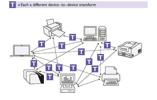
Figure 4: Device Dependent Transformation
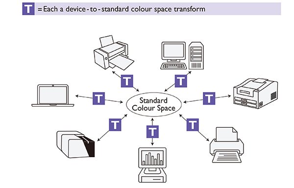
Figure 5: Device Independent Transformation
But what should the standard color space look like? And who should setup the specification of the standard color space? Fortunately, ICC has this covered. ICC stands for International Color Consortium, and was established in 1993 by eight industry vendors. The purpose of ICC is to create, promote and encourage the standardization and evolution of an open, vendor-neutral, cross-platform color management system architecture and components. And the outcome is the ICC profile specification. ICC profile is the key to achieve open source color management workflow. It contains information related to the device characteristic, and both forward and backward transformations from device to the standard color space, which is called PCS (Profile Connection Space) in ICC color transformation. ICC color transformation is illustrated in Figure 6.

Figure 6: ICC Color Transformation
But how can ICC color transformation be utilized in practice? Let’s look at the example in Figure 7. When a user scans a color from a scanner, it reads (R, G, B) = (42, 82, 171). If the user would like to print out the same color as the scanned color, ICC workflow will first transform the scanned color to (L*, a*, b*) = (51, 11, 43) in PCS by using scanner ICC profile. Then by using the printer ICC profile, (L*, a*, b*) = (51, 11, 43) is determined to be (C, M, Y, K) = (57, 29, 9, 0) for the printer. By comparing (R, G, B) = (42, 82, 171) from the scanner and (C, M, Y, K) = (57, 29, 9, 0) from the printer, the user will find the colors are very similar. This illustrates the overall ICC workflow.

Figure 7: Example of ICC Workflow
In this article, we have discussed the concept of color management and its goal to have a consistent color appearance across different devices. We also talked about color gamut and how to setup transformations between two or more devices. Lastly, we introduced ICC and ICC profile, and how ICC workflow is utilized in practice. In our next article, we will talk about who should really utilize ICC workflow and how it should be done.